How to edit a CAD file?
Let's create a function to add, change, and remove entities. In this example we use the Entities.dxf file. You can find it in ...\CAD .NET 14\Files.
By default, the CAD .NET folder is unpacked to Documents.
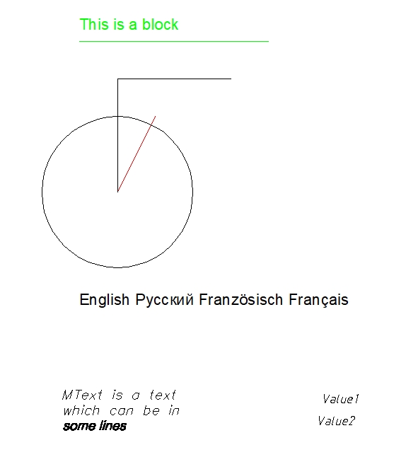
The following picture illustrates the Entities.dxf file by default.

- Add the
usingdirective with theCADImportandCADImport.FaceModulenamespaces.
using CADImport;
using CADImport.FaceModule;
More information about CADPictureBox
The CADPictureBox class is the basic implementation of the control element for displaying vector drawings. Visually CADPictureBox includes only area for drawing visualization and can be extended by the required control elements in the project under development.
To get more information about the CAD .NET controls, see What controls does CAD .NET have?
- Use the control element of the
CADPictureBoxclass:- Set the
Locationproperty asnew Point(10, 30). - Set the
BackColorproperty asColor.Black. - Set the
Sizeproperty asnew Size(995, 500). - Finally, add it to the form.
- Set the
...

CADPictureBox pictureBox1 = new CADPictureBox(){
  Location = new Point(10, 30),
  BackColor = Color.Black,
  Size = new Size(995, 500),
}

public Form1()
  {
    Controls.Add(pictureBox1);
    InitializeComponent();
  }
- Add a new button. Name it
EditDrawing. Then create theEditDrawing_Clickfunction to load a CAD file by click. Also, add theOpenFileDialogcomponent and name itopenFileDialog1.
private void EditDrawing_Click(object sender, EventArgs e){
- Create a new instance of the
CADImageclass. Also, change theBackgroundColorproperty of thisCADImageinstance.
  CADImage vDrawing = CADImage.CreateImageByExtension(@"Entities.dxf");
  vDrawing.LoadFromFile(@"Entities.dxf");
  vDrawing.BackgroundColor = Color.Azure;
We recommend creating a new drawing object using CreateImageByExtension in case of importing from an existing file or stream.
- Create a new instance of the
CADLineclass:- Add this entity to the drawing with the
AddEntitymethod. - Set the
Pointproperty asnew DPoint(50,0,0). - Set the
Point1property asnew DPoint(50, 70, 10). - Set the
LineWeightproperty as1. - Use the
Loadsmethod to fill the internal data of the entity to prepare it for drawing.
- Add this entity to the drawing with the
  CADLine vLine = new CADLine();
  vDrawing.CurrentLayout.AddEntity(vLine);
  vLine.Point = new DPoint(50, 0, 0);
  vLine.Point1 = new DPoint(50, 70, 10);
  vLine.LineWeight = 1;
  vDrawing.Converter.Loads(vLine);
- Edit the
ColorandLineWeightproperties. Use theLoadsmethod to fill the internal data of the entity to prepare it for drawing.
  vDrawing.CurrentLayout.Entities[1].Color = Color.Blue;
  vDrawing.CurrentLayout.Entities[1].LineWeight = 2;
  vDrawing.Converter.Loads(vDrawing.CurrentLayout.Entities[1]);
- Remove the third entity using
RemoveAt(). This method removes the element with the specified index from theEntitieslist.
vDrawing.CurrentLayout.Entities.RemoveAt(2);
- Use the
GetExtentsmethod to recalculate drawing extents.
vDrawing.GetExtents();
- Declare the local variable
vRectand specifyRectangleFas its type. This variable stores four floating values that represent the location and size of a CAD file. Use the following code to fit the CAD file topictureBox1. Finally, render the result with theDrawmethod.
RectangleF vRect;
double vRatio = (double)(vDrawing.AbsHeight * pictureBox1.ClientSize.Width)/ (vDrawing.AbsWidth * pictureBox1.ClientSize.Height);
if (vRatio > 1)
  vRect = new RectangleF(0, 0, (float)(pictureBox1.ClientSize.Width / vRatio), (float)pictureBox1.ClientSize.Height);
else
  vRect = new RectangleF(0, 0, (float)pictureBox1.ClientSize.Width, (float)(pictureBox1.ClientSize.Height * vRatio));
vDrawing.Draw(pictureBox1.CreateGraphics(), vRect);
You have created the function to add, change, and remove entities.
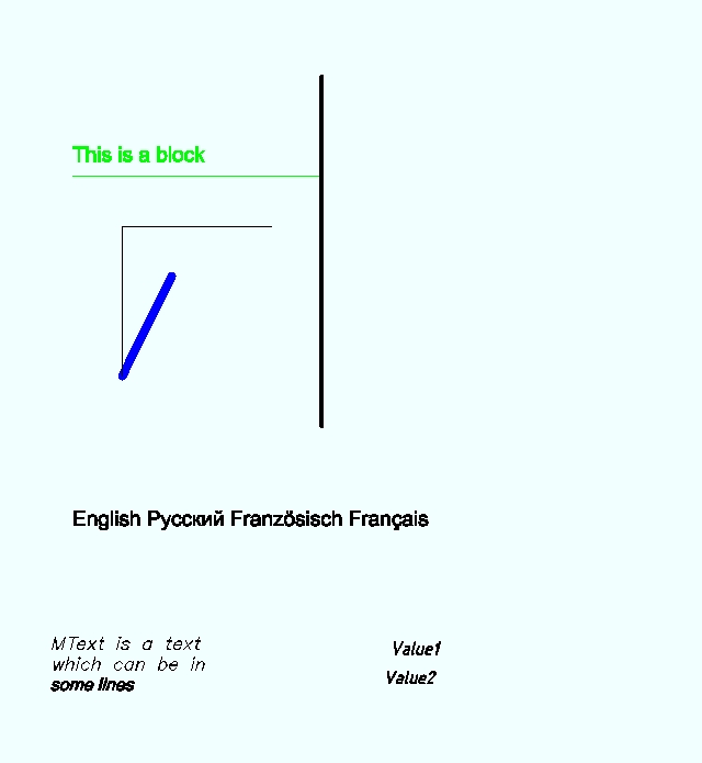
The following picture illustrates the result.

The full code listing.
...
using CADImport;
using CADImport.FaceModule;

namespace WindowsFormsApp1
{
    public partial class Form1 : Form

    {
        CADPictureBox pictureBox1 = new CADPictureBox()
        {
            Location = new Point(10, 30),
            TabIndex = 10,
            BackColor = Color.Black,
            Size = new Size(995, 500)
        };
        public Form1()
        {
            Controls.Add(pictureBox1);
            InitializeComponent();
        }
        private void EditDrawing_Click(object sender, EventArgs e)
        {
          CADImage vDrawing = CADImage.CreateImageByExtension(@"Entities.dxf");
          vDrawing.LoadFromFile(@"Entities.dxf");
          // Changing background color
          vDrawing.BackgroundColor = Color.Azure;
          // Creating a new entity - line
          CADLine vLine = new CADLine();
          vDrawing.CurrentLayout.AddEntity(vLine);
          vLine.Point = new DPoint(50, 0, 0);
          vLine.Point1 = new DPoint(50, 70, 10);
          vLine.LineWeight = 1;
          vDrawing.Converter.Loads(vLine);
          // Removes the circle entity from the Entities.dxf drawing
          vDrawing.CurrentLayout.Entities.RemoveAt(2);
          // Editing the entity
          vDrawing.CurrentLayout.Entities[1].Color = Color.Blue;
          vDrawing.CurrentLayout.Entities[1].LineWeight = 2;
          vDrawing.Converter.Loads(vDrawing.CurrentLayout.Entities[1]);
          // Recalculates the extents of the drawing
          vDrawing.GetExtents();
          // Adjusting visualization sizes to the control area
          RectangleF vRect;
          double vRatio = (double)(vDrawing.AbsHeight * pictureBox1.ClientSize.Width) / (vDrawing.AbsWidth * pictureBox1.ClientSize.Height);
          if (vRatio > 1)
            vRect = new RectangleF(0, 0, (float)(pictureBox1.ClientSize.Width / vRatio), (float)pictureBox1.ClientSize.Height);
          else
            vRect = new RectangleF(0, 0, (float)pictureBox1.ClientSize.Width, (float)(pictureBox1.ClientSize.Height * vRatio));
          vDrawing.Draw(pictureBox1.CreateGraphics(), vRect);
        }
    }
}